Check valves, also known as one-way valves or non-return valves, are critical components in piping systems. Their main function is to allow fluid (liquid or gas) to flow in only one direction and to prevent backflow. Whether you’re interpreting engineering drawings, P&ID diagrams, or hydraulic schematics, understanding check valve symbols, non return valve symbols, and flow direction is essential for proper system design and troubleshooting.
What Is a Check Valve (One-Way Valve)?
A check valve also called a one-way valve or non-return valve—is a mechanical device that permits flow in one direction while automatically preventing reverse flow. They are used in water supply systems, fuel systems, HVAC, hydraulic circuits, and more. Depending on the application, various types of check valves are used, such as swing check valves, ball check valves, and lift check valves.
Standard Check Valve Symbols
1. Basic Check Valve Symbol
The most common symbol for a check valve or non return valve is an arrow with a line across the tip or a triangle pointing in the flow direction with a vertical bar:
--->| (Flow from left to right allowed)This shows that flow is allowed from one direction (left to right) and blocked in the reverse direction.
2. Check Valve Symbol with Flow Direction
Many schematics indicate flow direction directly with arrows. When flow direction must be clear, a unidirectional arrow is included along the pipeline with the valve symbol:
-->|--> (Shows both the valve function and direction of flow)This symbol helps engineers avoid incorrect installation of a check valve or non-return valve.
Specialized Check Valve Symbols
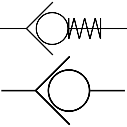
3. Ball Check Valve Symbol
A ball check valve uses a spring-loaded ball to block reverse flow. The symbol typically includes a circle (representing the ball) and a spring:
o|>--- (The "o" may represent the ball)4. Swing Check Valve Symbol
Swing check valves are shown with a pivoting flap, often represented as a curved or angled line within the valve body:
-->)--- (Implied swinging disc)5. Lift Check Valve Symbol
Lift-type check valves are similar to globe valves but with a flow-blocking mechanism that lifts up. The symbol resembles that of a globe valve with an added arrow or vertical line.
Check Valve in P&ID and ISO Diagrams
In P&ID diagrams, check valves (non return valves) are represented based on the ISA or ISO standards. They can be annotated with text to specify type (e.g., “Check Valve”, “Non Return Valve”, “NC” for normally closed, or flow direction).
In ISO 1219 hydraulic diagrams, the symbol usually includes a triangle and a bar, clearly showing direction:
►| (Triangle points in allowed flow direction)Best Practices: Flow Direction and Installation
- Always check for flow direction arrows in the drawing and on the physical valve body.
- Ensure correct orientation during installation to avoid flow blockage or system malfunction.
- Use labels or tags if necessary to avoid confusion in complex systems.
Conclusion
Check valves (one-way valves or non return valves) are simple yet vital components in many fluid systems. Understanding their symbols—whether basic or specialized—and knowing how flow direction is indicated in diagrams helps engineers and technicians ensure safe and efficient operation.
Need help selecting or interpreting check valves for your project? Contact us for expert guidance and reliable product options.
